Drummond Biles
Mechanical Engineering PhD Candidate | University of New Hampshire
UNIS
During the fall of 2011 an opportunity arose for myself to write a research proposal with the research lab I was working in, MIRL, and a university located in Svalbard, Norway. This proposal was to assist in the development of a procedure to calibrate all-sky cameras. This proposal was funded by UNH through the international research opportunity program (IROP). I then spent the summer of 2012 working out of the University Centre in Svalbard and the Kjell Henriksen Observatory in Longyearbyen, Svalbard which you can see on the map to the left.


The all-sky camera utilizes a fish eye type lens to achieve a field of view over 120 degrees. This is excellent for studying events in the atmosphere from ground utilizing optics as it gives you images such as the one displayed to the left with a very wide FOV. The challenge is in the calibration of these cameras, as the wide FOV makes traditional calibration procedures unusable. Traditionally a camera is pointed at a uniform light source, such as the green calibration sphere in the pictures below., and an image is taken at approximate operating characteristics. Thus the known intensity and number of counts observed can be compared and a calibration map can be produced. With an all-sky camera the lens must be mounted inside of the calibration device in-order to fill the entire FOV with the uniform light source. This leads to problems as camera could get direct light from the integration sphere input light and the light characteristics have not been defined inside of the spheres exit plane.

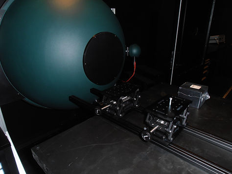

The picture to the right shows the initial design of the calibration setup. The camera would be mounted on the adjustable lab jacks (4), and then positioned to the calibration sphere (1) with the use of linear rails (5). A clear plastic dome (2) would be inserted into the sphere to mimic the viewing domes on the observatory. Finally a "moon blocker" is placed to the right of the camera to block direct light from the input source.
Beginning to assemble the system
A spectrum analyzer was placed on the setup and position to where the camera would be in order to detail what the camera will be seeing. This data was then used for the calibration procedure
Final pictures of all-sky camera calibration setup
To view my reports and presentation on this work please see the poster and presentation I have provided below
Sigernes, Fred; Holmen, SE; Biles, D; Bjørklund, H; Chen, X; Dyrland, M; Lorentzen, DA; Baddeley, L; Trondsen, T; Brändström, U; ",Auroral all-sky camera calibration,"Geoscientific Instrumentation, Methods and Data Systems",3,2,241-245,2014,Copernicus GmbH