Drummond Biles
Mechanical Engineering PhD Candidate | University of New Hampshire
NEAT Tunnel - Thermal Wall Plate
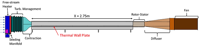
The thermal wallplate, which sets the wall temperature of the tunnel, was an essential component to develop for my PhD research. Precise control of the wall boundary condition would allow for the setup of numerous forced convection studies. The following details the development of the thermal wallplate from an initial prototype design built for the wind tunnel below to the full scale design.
Prototype


Final Design


The system was then assembled into the NEAT tunnel, and was ready for testing!
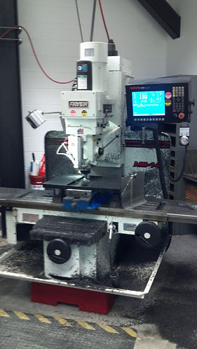
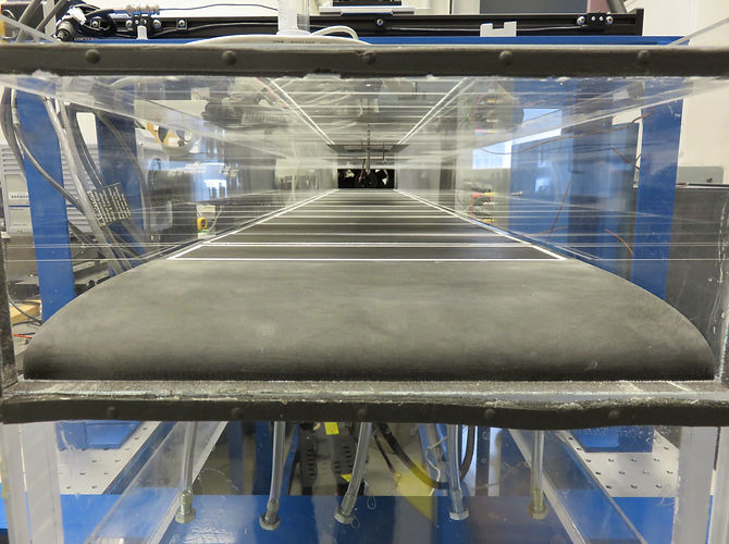
The prototype design was built for the wind tunnel pictured to the right. This tunnel has a much shorter development length (.45m) making it easier to manufacture a thermal wall plate for. A design consisting of two thermal wall plates was developed which could validate the thermo/mechanical design and controller setup.
All designed parts were then manufactured in house utilizing NC and CNC machinery.
The image to the left shows a mock up with the insulation installed into place.
The picture to the left shows the Al plates which sit into the insulation and act as thermal mass for setting a wall temperature.
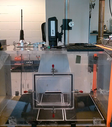
Initial validations were performed using an IR camera to quantify the spatial variability of the thermal wall plate. The setup is displayed below in SolidWorks and then in the figure to the left. A low spatial variability was key to the design as that would ensure the validity of a constant wall temperature boundary condition when compared to analytical results.
Temperature profiles in the wall normal direction were taken using a type J micro thermocouple shown below. This profiles could then be compared to analytical laminar flow solutions for validation as shown to the left.
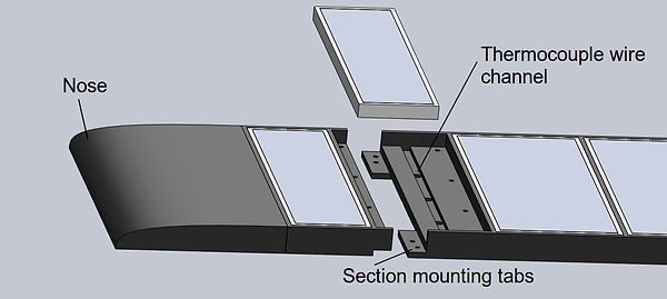
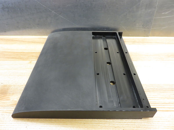
The final design of the thermal wallplate can be seen to the right. This design was an expanded version of the prototype to fit the entire length of NEAT tunnel.
The design incorporated interlocking sections due such that the design could be feasibly constructed. These sections were joined beneath the heated plate such that the top surface would remain smooth and limit the disruption to the flow.
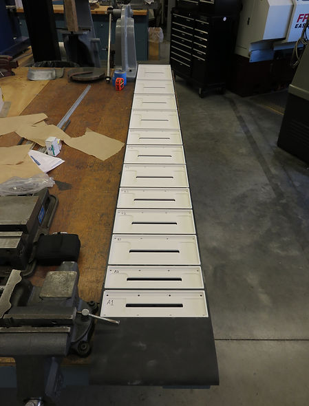
Upon complete the design I ordered all the material and got to work fabricating. Pictured to the left is all the blank plastic (Acetal) base sections.
The picture to the left details some of the pocket work that was done on the leading section of the thermal wallplate.
Intermediate section of the thermal wallplate frame.
Once all the frame sections and insulation pieces were complete a test assembly was performed, which is displayed to the left.
Each Al convective plate was then custom machined to fit within the insulation sections. This was then all test assembled, shown to the left.
The convective sections were then painted to increase the reliability of IR measurements and the entire system was assembled with wiring and all.
Finished front frame section of the thermal wallplate.
The insulation that sits into the wallplate frame is fabricated from calcium silicate. This was chosen for its high machinability and very low thermal conductivity. Three of the twelve sections are shown in the image to the left.