Drummond Biles
Mechanical Engineering PhD Candidate | University of New Hampshire

FPF as seen from the outside pictured above. The test section runs the length of the second floor with the inlet pictured at the left end of the building.
Flow Physics Facility
The Flow Physics Facility (FPF) is the worlds largest boundary layer wind tunnel. The tunnel test section measures in at 6m wide by 2.7m tall by 72m long. This long development fetch allows for boundary layers to grow up to 1m in thickness. At the rear of the tunnel sit two 400-horsepower fans, each moving 250,000 cubic feet of air per minute. This results in the ability to produce Reynolds numbers from 2x10^5 up to 5x10^7. The length and scale of the tunnel also allows for testing of large engineering systems while maintaining low blockage ratios and the unique ability of examining far downstream of an object to stud wake parameters.
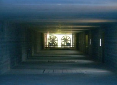
An image looking down the length of the tunnel towards the fans.
Development of Particle Image Velocimetry
PIV is a non-intrusive experimental technique used to measure fluid velocity. The technique involves a camera imaging a laser sheet that was been arranged in seeded flow. For the case I will describe oil droplets produced from a fog machine are injected into the flow and are passively advected down the length of the tunnel, which creates a seeded flow. A laser in then arranged beneath the tunnel and creates a laser sheet through a window in the tunnel test section floor. The sheet is arranged in the wall normal, streamwise plane. A camera focused on the laser sheet sits outside the tunnel viewing through a side window. This camera is then able to capture the laser light which is reflected off of the oil droplets in the flow. The video to the left shows captured PIV images where the image intensity has been colored green. If these images are taken close together in time a vector map can be created between adjacent image pairs which describes the displacement of groups of oil droplets. Knowing the time between images velocity vectors computed.
This technique is excellent for determining flow velocities as it is non-intrusive (does not disturb the flow) and measures a velocity field instead of just a single point. The spatial resolution of the system is limited by the camera optics and the desired field of view. The temporal resolution of the system is limited by the rep rate of the camera and laser. I will discuss the development of the PIV system for each component; seeding mechanism, laser/sheet optics, and camera.
The following video details the entire system assembled into the FPF.


FPF
Seeding Mechanism
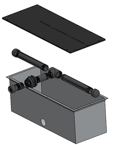
Solid model of seeding mechanism, where fog is introduced through the bottom and enter into the flow through the top slot.


The following pictures detail the fabrication process done to create the seeding mechaism

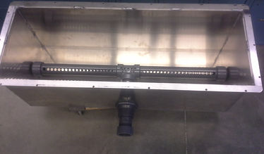
Image detailing the procedure for cutting the seeding slot, which would introduce fog into the air flow.

Inside of the plenum a fog manifold was created that had varying hole diameters across its length to ensure even fog distribution across the entire slot width.

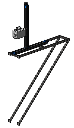
Laser and Sheet Forming Optics
The laser system was assembled beneath one of the window downstream of the seeding mechanism. The image to the right details how the laser was arranged and the overall beam path before creating a laser sheet which the high speed camera is focused on.
Camera System
The highspeed camera sat outside of the wind tunnel and viewed in through a window which looked across the width of the tunnel. The camera was aligned with the above detailed laser sheet.