Drummond Biles
Mechanical Engineering PhD Candidate | University of New Hampshire
Teaching
Over my time in graduate school I had been in multiple teaching environments, from large lecture halls to machine shops. In all aspects of my teaching I strive to be engaging and give the students an understanding of why the material is important. For more description of my Teaching Philosophy click here.
The following is a list of projects that I have developed or helped to develop which demonstrate type of I work I ask students to do.
Intro to Machine Shop
As an undergraduate engineering student I quickly found my way into a machine shop and worked for a physics lab developing instrumentation. Knowledge of fabrication methods has served me well as I personally build my experimental setups. I also it is an important skill for anyone working on the design of physical components. The forsight of manufacturing procedures helps to inform the design and make it realistic and practical. I wanted to be sure every engineering student had access to this and so I worked with several other students and professors to develop a machine shop training class. This class runs for three weeks and gives students all the basic safety skills on manual lathe and milling machines. The students then work with the teaching assistants for the class and the lead machinist on developing and fabricating parts for research projects and senior projects.
Computer Aided Engineering: Design and Build Project


As a teaching assistant for the senior level Computer Aided Engineering class I assisted in developing a series of projects. The first project that I worked to develop was a design and build project. The objective was to have the student complete a full design and analysis utilizing the computer package SolidWorks, which would then be fabricated and tested in the scenario that it was designed for. The teams with the lightest mechanism to be successful would then be awarded bonus points.
The first version of this was a three bar linkage system to convert rotational motion into reciprocating translational motion. The students were provided with basic dimensions as shown in the schematic to the left, yet some of the dimensions (such as beam lengths) were left blank. The students first task was to solve the problem kinematically and determine all base dimensions. The next step was then to design beams (L1, L2, L3, L4) and pins (O, A, B, C, D, E) to withstand moving a known mass a certain distance under a known spring coefficient at E.
Each student group developed a solid model of their mechanism as seen to the left. A solid model of the basic mount points and connections (ie motor, piston) were provided to the students to design around.

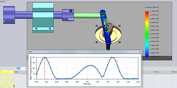
Using what they had learned in the different laboratory assignments they performed a motion based stress analysis to optimize the design of each member for lightest weight.
The following is a collection of images/video of the different design that the students developed. The greatest part of this assignment is seeing the wide variety of designs that are created by the students


CAE_proj2_mechanism
Computer Aided Engineering: Stress Analysis with FEA


GoKart
When creating a CAE project I always want to get the students to perform analysis on true scenarios from real world data. Therefore when I was approached by an alumni who races in a go-kart league with a broken wheel spindle and complementary data I could not resist putting it all into a project for the students. The video to the left shows the crash that occurred. From the on-board system we obtained a time series of speed and acceleration in all three directions which the students could then use to determine impact force.

The pictures to the left shows the go-kart which was crashed and points out the spindle which we had the students perform a stress analysis on. The spindle was deformed and had a hairline fracture where it mounted to the go-kart body. The task for the students was to determine if the crash was outside the limits of the component of if the crack came from a manufacturing defect.

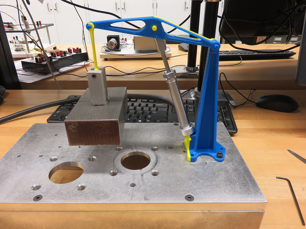
Computer Aided Engineering: Design and Build version 2

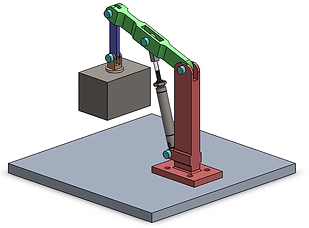
The design and build project was very successful with engaging the students and so a variation was developed so that the project did not become over used. The above images display the solid model of the system. This time the students had to create the components of a crane and lift a 3kg weight. Again overall project dimension were provided as well as the pneumatic lifting mechanism. The students designed the red, green and blue members. There task was to make these members as lift as possible while still being able to fully lift the mass. The following is a collection of pictures of the final student designs.